Overview
In my previous post "Artemis Synthesizer 1 - Testing the TDA2822 Audio Amplifier" I introduced the Artemis Project and that the Boston University EDF is putting together a music synthesizer/sequencer kit for the program. Now that we can driver 8 Ohm speakers effectively lets try to interface the digital world with the analog world.
To interface between the digital and the analog we normally use something called a DAC (Digital to Analog Converter). There are a variety of different DACs. For example, there is the R-2R type DAC which is a ladder of resistors with digital inputs at different points. R-2R DACs are cheap, but are pin expensive; however, they can be extremely useful for reading off multiple switches or other such setup using the minimal number of microcontroller pins. For more on R-2R DACs see my write up on NOMIS, my Simon Clone.
For this application an R-2R DAC would be noisy and very difficult to get accurate readings off of. Instead I will be using a digital DAC IC from Microchip called the MCP4921, which has an SPI (Serial Peripheral Interface) bus.
Table of Contents
Basic Design^
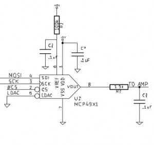
The basic design is simple and sort of stolen from Adafruit's Wave Shield, which uses the same DAC chip. The main thing to note here is that on the output of the DAC is a 1st Order Low Pass Filter with a cutoff frequency of about 11kHz. What this allows us to do is to have a sample rate of 22kHz, which allows us to construct waves up to 11kHz while still obeying the Nyquist frequency. Realistically all of the waves we care about will be lower than 11kHz, so we should be able to reconstruct the waves we want with decent accuracy while also removing high frequency noise and reflections (and without aliasing)!
Schematic^
Parts List^
- 1 MCP4921 SPI DAC
- 1 100k Ohm Resistor
- 1 1.5k Ohm Resistor
- 1 .1uF Capacitor
- 1 .01uF Capacitor
- A microcontroller (preferably an ATMega328P, which is contained on the Arduino)
- Some way of seeing the output waves

Interfacing Over SPI^

Talking over the SPI bus as a master is extremely simple when you are using an AVR. The standard is very flexible, which is where you need to be very careful. Wikipedia's article is very useful for understanding the basics of the SPI bus. I also found RocketNumberNine's article on using the SPI bus with AVR microcontrollers in particular to be extremely useful. If you are using the Arduino environment all of the register manipulation is hidden and it is as simple as typing:
|
1 2 |
SPI.begin(); SPI.transfer(some_byte_of_data); |
However, once you abandon the world of Arduino the problem remains pretty easy, but you follow the normal microcontroller workflow:
- Find peripheral you want to use
- Read the datasheet on how to interface with that peripheral
- Write a few functions for initialization and interfacing
- (OPTIONAL) Make it interrupt driven, if possible/logical.
So lets get our ATMega328P datasheet and write those functions. I already wrote the functions, and they are accessible on github . The functions for the SPI communications are slightly modified versions ofRocketNumberNine's whose article should be referenced.
For the MCP492x family of SPI bus DACs we have a very simple protocol, which is split up between two octets, which means it will take two calls to our SPI transmission function to send the data. It is also important to note that the data should be sent MSB (Most Significant Bit) first. Also, the top 4 bits are configuration bits. I use the configuration 0x3 (0b0011) which turns of the Vref Buffer, Enables Output, and sets the gain stage so that it is only Vref*D/4096 instead of 2*Vref*D/4096. On the MCP4921 you don't need to worry about channel B so the channel select bit should always be 0.
Top Byte
| 15 | 14 | 13 | 12 | 11 | 10 | 9 | 8 |
| Select DAC Channel (0 = A, 1 = B) | Vref Input Buffer Control (1 = Buffered, 0 = Unbuffered) | Output Gain Stage (1x = 1, 2x = 0) | Output Power Down (1 = Output Power Down Control bit, 0 = Output buffer disabled, Output is high impedance) | D11 | D10 | D9 | D8 |
Lower Byte
| 7 | 6 | 5 | 4 | 3 | 2 | 1 | 0 |
| D7 | D6 | D5 | D4 | D3 | D2 | D1 | D0 |
The interface code I wrote (available here) ends up looking like this:
|
1 2 3 4 5 6 7 8 9 10 11 12 13 14 15 16 17 18 19 20 21 22 23 24 25 26 27 28 29 30 31 32 33 |
#ifndef DAC_DDR #define DAC_DDR DDRB #endif #ifndef DAC_PORT #define DAC_PORT PORTB #endif #ifndef DAC_PIN #define DAC_P PB2 #endif #define SETUP_DAC DAC_DDR |= (1< <DAC_P) // Set up #CS for the DAC #define SELECT_DAC DAC_PORT &= ~(1<<DAC_P) // Set #CS for DAC low, selecting it #define DESELECT_DAC DAC_PORT |= (1<<DAC_P) // Set #CS for DAC high, deselecting it void writeMCP492x(uint16_t data, uint8_t config) { // Take the top 4 bits of config and the top 4 valid bits (data is actually a 12 bit number) and or them together uint8_t top_msg = (config & 0xF0) | (0x0F & (data >> 8)); // Take the bottom octet of data uint8_t lower_msg = (data & 0x00FF); // Select our DAC SELECT_DAC; // Send first 8 bits sendSPI(top_msg); // Send second 8 bits sendSPI(lower_msg); DESELECT_DAC; } |
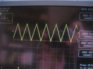
To create this function I use some bit shifting magic, but basically I take the 16 bit data variable (which should only contain 12 bits of significant information), throw out the top 4 bits, then mask over the configuration bits. Once this is done you send that message and then send the lower 8 bits of the 16 bit data variable. Set your DAC select pin low, sned the messages and then set it high again. Message sent and indeed upon hooking up an O-scope I got the waves I was sending.
Results^
So first I sent a basic triangle wave, generated algorithmically to the MCP4921, the output was very nice and impressive:
I then went to generating a ramp and here are the results of it playing through the speaker and amplifier board we designed in the last post. Here is the video:
Problems^
Throughout all of this I found a few problems. When I move from 5V down to 3.3V the MCP4921 runs perfectly fine until it gets hooked to the input of the TDA2822 Amplifier. Some random noises will come out of the speaker, but nothing very meaningful. This is interesting and concerns me a little. I am trying to figure out how to fix this, it seems like it might be a current draw problem, I might want to put a multimeter in series with the 3.3V supply from the Arduino to see what the current draw is.


What is the SPI speed?
What is the max band width of the DAC.
What is the freq of the triangle wave on the scope.
Hi,
Thank you for the article. I have a question:
In the parts list, why do you mention 1 0.1 uF and 1 0.01 uF caps, when on the schematic there are 3 o.1 uF caps?