Overview

For Boston University's Artemis Project, a STEM education summer program for female rising high school freshmen, the BU Electronics Design Facility designed a synthesizer kit and ran a two day soldering workshop for the students. The whole kit was put together over about a 1 month period.
The Artemis Synthesizer is a basic 12-bit resolution synthesizer which has an output sample rate of 22kHz. The output audio is filtered at 11kHz to satisfy Nyquist and prevent weird aliasing and reflections in the output audio. Internally the synthesizer generates sound using a predetermined wave table, which can be changed and recalculated if desired. By default, the wave table contains a sine wave with 256 steps, but harmonic sound data can be programmed into the synth kit using our web interface.
The synthesizer contains two interactive modes and one mode for the optical communication link. These modes are: a keyboard mode, which contains 4 scales (C major, C pentatonic, C blues and C minor) and has 8 available keys; and a sequencer mode, which can hold eight 8-step by 8-note sequences. In sequencer mode, new sequences can be entered from the web interface.
The optical link, which is kindly called the "Optoloader" has its own separate mode and detects timed transitions between black and white from a computer monitor. The light levels are taken in on a photo-transistor and transitions detected using an analogue comparator interrupt with the comparison set at V_bat/2. The data is encoded using BiPhase Mark Code which encodes the clock with the data. The link is generally reliable when the monitor is set to a high brightness and a low speed is used. Mostly it allows for us to have a kit which is interactive with minimal programming experience and can still be changed and played with long after they leave. Thus the web interface which was developed by Sam Damask becomes very important for the end goal of our project.
The development team contained:
- Christopher Woodall [Me] who designed the kits and wrote the firmware
- Eric Hazen who reviewed my designs, advised my decisions and wrote the assembly instructions and parts list
- Sam Damask who wrote the web interface code.
Along the way I documented the process, explaining a few design decisions and experiments. I will go over vital information and reference the posts which contain relevant information as I go along:
- Artemis Synthesizer 1: Testing the TDA2822 Audio Amplifier
- Artemis Synthesizer 2: Interfacing with the MCP4921 SPI DAC
- Artemis Synthesizer 3: Basic I/O with Buttons and LEDs
- Artemis Synthesizer 4: Post-Mortem
- The Optoloader: Transmitting Data With a Blinky Box (Coming Soon)
- Fixed-Point Arithmetic: Fast Fractions using Integer Arithmetic (Coming Soon)
Read on!
Table of Contents
Hardware^

Schematic^

The schematic PDF file is available. You can also get the KiCAD from github.
PCB^

The gerbers and KiCAD files are all available on the github for the Artemis Synthesizer project. The picture above is the top layer and top silkscreen. To see the rest I suggest going to the github and opening my gerber files, or using KiCAD to view my design files.

The boards went out to manufacture from Sierra Circuits and their No Touch PCB deal. We operated well within their tolerances and in general the boards came back very well. There was one hairline short, that we could not see on one board out of the 30 that were used. No kits given to the Artemis students had any manufacturing faults. In fact, only the first board we used had a manufacturing fault, which was wound, cut and mended. I would use Sierra again, but I would think about paying for electrical testing. Also, they can be rather expensive, but they have a very fast turn-around and are a US board house. Our time restraints were very limited seeing as our boards went out to board house about 2 weeks before the event, leaving us one week, after turnaround, to put everything together and fix up the final firmware.
In the future, for longer timescale runs I would think about using Seeed or Itead with e-testing. However, I really would like to use a US board house, so it completely depends on quantity of boards for my next kit run. If I have enough to make a US board house cheap, I might choose a US board house a foreign board house.
Bill of Materials^

The bill of materials is available in the git repo and as a Google Document. All of the prices listed are for price breaks for quantity 50 of the board. In addition to what is listed you need 2 AA batteries. Total cost per board came out to $15.58 per board and our PCBs costed $10 per board, leaving us at a mark of $25.58 per board. Also, the shipping costs will be higher due to two separate distributors. Future revisions will likely all be from the same distributor.
| REFERENCE | VALUE | DISTRIBUTOR | DISTRIBUTOR # | Unit Cost @ qty 50 |
|---|---|---|---|---|
| SW2. SW3, SW4, SW5, SW6, SW7, SW8, SW9, SW10, SW11 | Momentary On Pushbutton | Mouser | 611-PTS125SM85-LFS | $0.20 |
| SP1 | SPEAKER | Digikey | 102-2502-ND | $1.81 |
| IC1 | ATMEGA328P | Mouser | ATMEGA328P-PU-ND | $1.95 |
| U1 | MCP4921 | Mouser | MCP4921-E/P-ND | $1.64 |
| RV1 | 1K | Mouser | 652-3352T-1-102LF | $0.97 |
| U2 | TDA2822M | Digikey | 497-8863-5-ND | $1.29 |
| BT1 | BATTERY | Mouser | 12BH325/CS-GR | $1.11 |
| STANDOFFS (UNTESTED, ONLY A SUGGESTION) | Circuit Board Hardware - PCB 3/16 HEX 1" LNGTH ALUM 440 THREAD (UNTESTED) | Mouser | 728-FC2065-440-A | $0.27 |
| D3, D4, D5, D6, D7, D8, D9. D10 | LED | Digikey | 754-1264-ND | $0.08 |
| C1, C5, C6, C7, C8, C11, C12, C13, C14 | .1uF | Digikey | BC2665CT-ND | $0.05 |
| J1 | USB B PTH | Mouser | 737-USB-B-S-RA | $0.49 |
| X1 | 16MHz | Digikey | 631-1108-ND | $0.38 |
| C2,C3 | 22pF | Mouser | 140-50N2-220J-RC | $0.08 |
| D1, D2 | 3V6 | Digikey | 568-7951-1-ND | $0.08 |
| C9 | .01uF | Digikey | 478-4862-ND | $0.19 |
| C10 | 10uF | Digikey | 399-6100-ND | $0.06 |
| R2, R3 | 68 | Digikey | S68QCT-ND | $0.02 |
| R9 | 100k | Digikey | S100KQCT-ND | $0.02 |
| R12, R13 | 1K | Digikey | S1KQCT-ND | $0.02 |
| R15, R16 | 4.7 | Digikey | S4.7QCT-ND | $0.02 |
| R1 | 2.2K | Digikey | S2.2KQCT-ND | $0.03 |
| R4 | 36K | Mouser | 660-MF1/4DCT52R3602F | $0.06 |
| R11 | 47K | Digikey | S47KQCT-ND | $0.03 |
| R8 | 10K | Digikey | S10KQCT-ND | $0.03 |
| R10 | TEPT4400 | Mouser | 782-TEPT4400 | $0.54 |
| R14 | 1.5k | Digikey | S1.5KQCT-ND | $0.03 |
| IC1 SOCKET | 28PDIP Socket | Mouser | 571-1-390261-9 | 0.32 |
| J2 | AVR-ISP-6 (2x3 .1” header) | stock? | stock? | 0 |
How Does It Work?^
Block Diagram^

Button Inputs^

There are a total of 10 button on the synthesizer board; however, there are two sets of buttons: the keyboard, made up of 8 buttons on Ports D and B (6 on D, 2 on B); and the 2 settings buttons, both on Port C. To make reading all of these buttons easier I wrote macros to indicate the button ports, pins, DDRs and their individual bitmasks. Then I wrote three functions: one to return the value of a given button and return its value called readButton(); the other two were readKeyboard() which returns a uint8_t with all 8 keyboard keys, in order, and readSettings() which returns a uint8_t with the least significant 2 bits indicating the state of the settings buttons.
The macros are defined as follows. The bit masks and similar "magic strings" will become obvious when you inspect the schematic. For example, BUTTON0 is on Port D Pin 0, thus its bit masks will be "0x01" (hex). In this case, "0x01" indicates that the least significant bit (the 0 bit) is set to 1. Likewise, BUTTON1 is on Port D Pin 1, so the 1 bit needs to be set and the bitmask becomes "0x02".
|
1 2 3 4 5 6 7 8 9 10 11 12 13 14 15 16 17 18 19 20 21 22 23 24 25 26 27 28 29 |
// Define the masks and port locations for the button // Button Locations: // 0-5: Port D // 6-7: Port B // 8-9: PORT C #define BUTTONS_0to5_bm 0b00111111 #define BUTTONS_0to5_PIN PIND #define BUTTONS_0to5_PORT PORTD #define BUTTONS_0to5_DDR DDRD #define BUTTON0_bm 0x01 #define BUTTON1_bm 0x02 #define BUTTON2_bm 0x04 #define BUTTON3_bm 0x08 #define BUTTON4_bm 0x10 #define BUTTON5_bm 0x20 #define BUTTONS_6to7_bm 0b00000011 #define BUTTONS_6to7_PIN PINB #define BUTTONS_6to7_PORT PORTB #define BUTTONS_6to7_DDR DDRB #define BUTTON6_bm 0x01 #define BUTTON7_bm 0x02 #define BUTTONS_8to9_bm 0b00110000 #define BUTTONS_8to9_PIN PINC #define BUTTONS_8to9_PORT PORTC #define BUTTONS_8to9_DDR DDRC #define BUTTON8_bm 0x10 #define BUTTON9_bm 0x20 |
Inorder to use the buttons we first need to set them up, which is to say we want to set the pins that the buttons are on to inputs and then activate the internal pull-up resistors. The following code does just that.
|
1 2 3 4 5 6 7 8 9 10 11 12 |
void setupButtons() { // Setup all Button pins to inputs with pullup resistors BUTTONS_0to5_DDR &= ~BUTTONS_0to5_bm; BUTTONS_0to5_PORT |= BUTTONS_0to5_bm; BUTTONS_6to7_DDR &= ~BUTTONS_6to7_bm; BUTTONS_6to7_PORT |= BUTTONS_6to7_bm; BUTTONS_8to9_DDR &= ~BUTTONS_8to9_bm; BUTTONS_8to9_PORT |= BUTTONS_8to9_bm; } |
Now come the fun functions that read the button states! readButton() works by taking a uint8_t which will range between 0 and 9 and indicates one of the 10 buttons. That value goes into a switch statement, which determines what value is returned. The instructions of the form (BUTTONS_YtoZ_PIN & BUTTONX_bm) == 0 read the PIN register for the port our button is on, and then masks it with the bit mask of the button we want. If the button is off (pulled high) the bit-wise & will return "1" and the function will return "0" since the button is not being pressed.
|
1 2 3 4 5 6 7 8 9 10 11 12 13 14 15 16 17 18 19 20 |
// Read off individual buttons by number. // See schematic for numbering convention. uint8_t readButton(uint8_t button_no) { // Use this to easily read off a button switch( button_no ) { case 0: return (BUTTONS_0to5_PIN & BUTTON0_bm) == 0; case 1: return (BUTTONS_0to5_PIN & BUTTON1_bm) == 0; case 2: return (BUTTONS_0to5_PIN & BUTTON2_bm) == 0; case 3: return (BUTTONS_0to5_PIN & BUTTON3_bm) == 0; case 4: return (BUTTONS_0to5_PIN & BUTTON4_bm) == 0; case 5: return (BUTTONS_0to5_PIN & BUTTON5_bm) == 0; case 6: return (BUTTONS_6to7_PIN & BUTTON6_bm) == 0; case 7: return (BUTTONS_6to7_PIN & BUTTON7_bm) == 0; case 8: return (BUTTONS_8to9_PIN & BUTTON8_bm) == 0; case 9: return (BUTTONS_8to9_PIN & BUTTON9_bm) == 0; default: return 0; } } |
The readKeyboard() and readSettings() functions are very similar, they just read off the appropriate PIN registers, align the data and return a uint8_t. The best way to understand these is to read up on port manipulation and look at the operations a little. As an aside, these should be inline functions in future revisions of the code.
|
1 2 3 4 5 6 7 8 9 10 11 12 13 14 15 |
// Dump the 8 keyboard buttons (bottom row of 8) into a uint8_t representing there state // 0 is pressed // 1 is unpressed // MSB -> LSB // BUTTON7 -> BUTTON 0 uint8_t readKeyboard() { return ((BUTTONS_6to7_PIN & BUTTONS_6to7_bm)<<6)|(BUTTONS_0to5_PIN & BUTTONS_0to5_bm); } // Dump the two settings buttons into a uint8_t with the lower two bits indicating state uint8_t readSettings() { return (BUTTONS_8to9_PIN & BUTTONS_8to9_bm) >> 4; } |
Here is a nice writeup on basic port manipulation for AVR microcontrollers: Suhas's Blog: AVR GCC Tutorial (1)
Digital-to-Analog Converter^

Once we know what note to play the waveform still needs to be generated. To do this we use the the MCP4921 12-bit Digital-to-Analog Converter (Datasheet), which has an SPI interface to communicate with the ATMega328P (Datasheet). I already went over the SPI interface and how you interface with this chip in "Artemis Synthesizer 2: Interfacing with the MCP4921 SPI DAC". Once I figured out how to write to the SPI bus as a master I ended up with this function:
|
1 |
void writeMCP492x(uint16_t data, uint8_t config); |
writeMCP492x() takes data, masks it down to 12 bits and sends the appropriate SPI message to the MCP4921. The MCP4921 then creates the appropriate analog voltage on its output pin. On the ATMega328P there is a Timer1 CompareA interrupt which takes place at a frequency of ~22kHz (or every .4545 microseconds), and calculates what the output voltage should be and then writes that 12-bit value to the MCP4921. With a sample rate of 22kHz we can reliably generate frequencies up to about 11kHz according to the Nyquist sampling theorem; however, I would personally avoid getting too close to that boundary.
To set up the sample rate the Compare A register for Timer 1 (OCR1A) needs to be set to some 16 bit value. The timing calculation is  . In this case our clock rate is 16MHz and no pre-scaler is being used so the timer resolution is 1/16MHz or .625 ns. The target time is going to be 45.45 microseconds so our OCR1A value is 727. Thus the following code will be used to initialize the timer compare interrupt. I suggest reading up on AVR Timer interrupts in the ATMega328P datasheet and over on AVR Freaks:
|
1 2 3 4 5 6 7 8 9 10 11 12 13 14 15 16 17 |
void setupSampleRate22kHz() { TCCR1A = 0; // set entire TCCR1A register to 0 TCCR1B = 0; // same for TCCR1B // set compare match register to desired timer count: // We want to compare at 22kHz // target time/timer resolution // (1/22kHz)/(1/16MHz) = 727 OCR1A = 727; // turn on CTC mode: TCCR1B |= (1 < < WGM12); TCCR1B |= (1 << CS10); // No prescaler // enable timer compare interrupt: TIMSK1 |= (1 << OCIE1A); } |
All that is left now is to figure out how to calculate the output of the waveform at any given point in time. I store the base waveforms in 256 sample long arrays of uint16_t, each of these has to be looked into at the given frequency. Such that at a rate of 22kHz you will output your waveform at x frequency. The way I do this is to use a uint16_t, which holds the position in the waveform array that is being output at any given point in time. This value is actually a fixed-point binary fraction with 8 integer bits and 7 fractional bits. I am not going to go into detail on fixed point arithmetic in this post, but will in a future post. The position is then updated by adding a predetermined value that corresponds to a frequency to the position (using addition mod 2^15). The fixed-point position is then truncated to its 8 bit integer value and used to lookup the output value in the table. For multiple notes these values are then added and scaled such that the output wont clip.
Amplifier^

The output of the DAC needs to be filtered and amplified before it reaches the speaker. First the DAC output signal goes through a low-pass filter with a corner frequency (cutoff) of 11kHz. This removes frequencies above 11kHz which is the maximum frequency we can reliably produce with the sample rate we have chosen (about 1/2 of the human hearing range). After being filtered the signal goes through a voltage divider to control the volume. More depth goes into the filtering and volume control, including calculations, in the post "Artemis Synthesizer 3: Basic IO with Buttons and LEDS".
The amplification circuit uses a TDA2822P and is covered in the post "Artemis Synthesizer 1 - Testing the TDA2822 Audio Amplifier", very little about this circuit changed from the time that post was written.
LED Display^

I talked about my design decisions for the LEDs in the post "Artemis Synthesizer 3: Basic I/O with Buttons and LEDs", and used a method explained and documented by Batsocks. The LEDs are set two to a pin with the anode of one attached to +3.3V and the cathode of the other attached to Ground. The remaining anode and cathode are then attached to the same microcontroller pin. When the pin is set to input it presents a high impedance (High-Z) and neither of the LEDs is forward biased. when the pin is set low the LED attached to +3.3V will turn on and when the pin is set high the other LED will turn on.
This method works perfectly in this case, but to drive any given pattern you need to abuse Persistance of Vision (POV) by updating the LED states such that the human eye cannot see the flicker. To do this, I used Timer2 to set up an LED update rate around 120Hz. This timer also maintains various state based information and handles button debouncing.
Optoloader^

The Optoloader is made up of a phototransistor and a voltage divider that sets the comparison point for the Analog Comparator. Every time there is a transition on the phototransitor it triggers an Analog Compare interrupt on the ATMega328P. The information is sent using BiPhase Marked Code (BMC), which encodes a clock with the data so that only one transmission line is needed for synchronous communications. BMC is very similar to Manchester encoding which is used in Ethernet. In general, BMC is rather robust and jitter resistant; however, in the case of our transmission link JavaScript can have some very disruptive jitter and currently the web interface communicates with the synthesizer using JavaScript.
The transmissions are sent using a protocol I invented which includes a Prologue (1 octet), Message Identifier (1 octet), Message (0-15 octets), Epilogue (1 octet). The messages are constructed as follows:
| Prologue | 00000001 |
|---|
| Message Identifier | bits 7-4 | bits 3-0 |
|---|---|---|
| Mode: 0011 - Sequencer, 1100 - Harmonics | Length of Message |
| Message (Sequencer) | Each bit in a byte indicates a note, each byte indicates a stage |
|---|
| Message (Harmonics) | bits 7-5 | bits 4-2 | bits 1-0 |
|---|---|---|---|
| Harmonic Number | Amplitude | "00" |
| Epilogue | 10000000 |
|---|
An in-depth post on the Optoloader will be coming soon as I revise the code and try to make the Optoloader code more reliable and faster.
USBasp Bootloader^

The USBasp bootloader based on the V-USB lowspeed USB library for Atmel Microcontrollers gives the synthesizer a USB interface for programming. This was used in development, but more so it also allows for future experimentation. The bootloader was edited a little bit by Eric Hazen of the BU EDF, the edited version is included in the git repository. I am not personally 100% sure of all of the edits made; however, there is a timeout, so the kit takes a few seconds to boot up.
One shortfall of this is that the current firmware is sufficiently complex such that someone who is just starting out might have a problem understanding it. What would be nice is to write some nice Arduino libraries that hid a lot of the complexity. This way someone with minimal experience could write functional code and add something to the synthesizer, thus creating a community of sorts.
The Kit^

Assembly Instructions and Parts Lists^
While putting a kit together I sat down and soldered one together, taking photos of each part and of each step in the process. Eric Hazen took these pictures to make the Assembly Instructions and Parts List. Having an illustrated parts list, in color, helps a lot considering that most of the people assembling the kit will not already know what a resistor is, or how to tell the polarization of a diode.
The assembly instructions were very helpful for the students that followed them; however, most followed the lead of their "helper" most of which had never put this particular kit together. In the future, I would like to make sure all "helpers" have experience putting the exact kit together.
The parts list an assembly instructions are available here and at the following sources:
Operation Instructions^

Once the kit is constructed there are a few modes that it can operate in: synthesizer mode, sequencer mode and optoloader mode. To get in and out of these modes and use each mode I made a operation manual, found here and show above. Move from mode to mode requires that you hold down some combination of buttons for a period of time. I had few options for changing modes, but in the future it would be nice to include some more convenient method of changing and indicating modes.
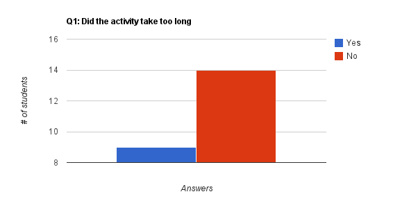
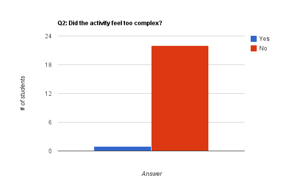
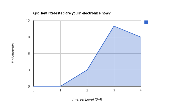
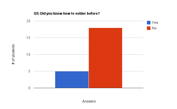
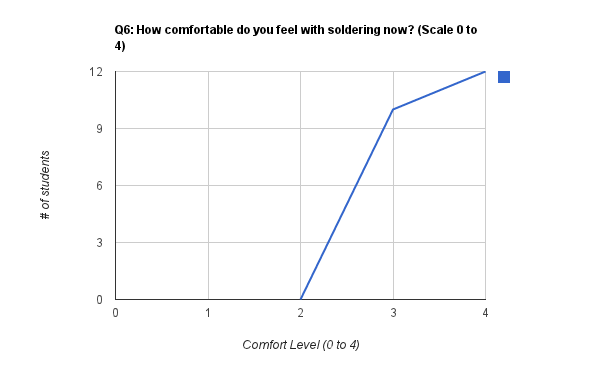
Reaction (Survey Results) ^

On the last day of the activity the students from the Artemis program took a survey, which consisted of 11 question. The following charts show the results of significant questions which were asked. Also presented are some select answers from the written questions.
By giving a survey we were able to understand how a sample group of 14-year-old female reacted to our kit. During the two days we had we picked up that they enjoyed it, but now we have some numbers. The reaction was positive and many more enjoyed electronics after compared to before. Also we seemed to have stamped out the fear of soldering. However, we did have a few conflicts.
While many enjoyed music as the topic for our kit a few would have preferred robots, or blinky leds. Some complained about the range of the synthesizer, which unfortunately is constrained by the button size and board size. Cost of manufacture would make it difficult to increase the size of the buttons much more. There were a few who found our "optoloader" to be unreliable and, as a result, found the second day of playing around with the synthesizer as boring. Many had problems soldering, but those who finished fast wanted something more complex. However, most of the remarks were satisfied and some even found it informative:
"I thought soldering was really fun, it gave me a chance to experience soldering and hardware engineering. I didn't really know what type of engineering field I should go into, but I can now considering hardware engineering in the future. and hardware engineering".
Graph Results^

Selected Answers from Various Questions^
Q8: How could we make this kit more entertaining?
- Maybe if the parts were more easier to put in, I wouldn't spend as much time trying to fit the pieces in.
- Maybe having more activities to do and more soldering.
- If the resistors were more easily identified by colors.
- We could of added more details to make it pretty and unique.
- There could have been more soldering because that was the best part of the activity.
- COLORFULL
- The kits were very fun. Maybe if the musical range was larger it would be better.
- It was interactive, and the pieces were easy to use.
Q10: What would you have preferred to build?
- Music was a good topic
- I didnt really like the music because it wouldn't program to my thingy and i had to keep getting lots of help.
- laser pointers
- Real speaking Robots.
- I would prefer to build a set of lights flashing on and off.
- i want to build something that could have different lights when you press the buttons'
- I love the idea of music, but we could've also built some kind of robot.
- maybe dance steps of like a tune
Conclusion^

Problems^

- We did not have 28-pin sockets so we used 2 14 pin sockets so some were not aligned properly. Check your BOM for parts and dimensions!
- No 8 pin sockets so if the DAC or Amp were put in wrong a lot of effort needed to go into rework. SOCKET ALL PINS.
- Some had issues getting R10 into place correctly and bending. It is a polarized part and needs to be put in right; however, the polarization is not labeled. Needs to be redesigned in future revisions. This will simplify the instructions
- Volume too low for the most part. Needs to be fixed in future revisions. A constant complaint.
- Web programming rig was effective, but I have some concerns about the actual usability of it. It is slow, and can be unreliable.
The Future^

The Artemis Synthesizer was certainly successful and will be used in future outreach activities by the EDF. Currently I am working on pitching it to the engineering department as a recruiting/introduction activity. I personally hope to order more boards for soldering workshops and after another revision or too it might eventually become a suitable instrument of sorts. There has also been talk of trying to put together a kickstarter campaign for this board. I would want to make more headway on cost reduction and Revision B first, before starting such a campaign, but I do think that this activity as is has potential for educational use, especially once I clean up the firmware a little more.
Moving forward some decisions need to be made. What is best for a low cost, low complexity kit is not necessarily the best for a full featured and useable instrument. I am still trying to figure out how to expand the capabilities of this kit such that it could be used as a low-cost instrument. Going forward I hope to find a nice compromise between functionality and simplicity.
That said I am also interested in making some more modular synths, guitar pedals and other less traditional electronic instruments. One of my larger obsessions is making an imitation, digital, Ondes Martenot, but I am also interested in using accelerometers and various methods of detecting air flow for music production. Ultimately, I want to bring my music training together with me engineering training, and expose people of various experience levels to both sides of my world.
Please contact me at chris.j.woodall+synth at gmail.com if you want to use these kits. I have some sample kits left and something could be worked out if you want to check one out. Otherwise, its open hardware, feel free to make your own run of PCBs! Just give me some credit!
Sources^
- Slides, Assembly Manual and Instructions
- Web Interface
- Github
Christopher Woodall (c) 2012

This work is licensed under a Creative Commons Attribution-ShareAlike 3.0 Unported License.
Do you know where I can purchase a PCB of the Artemis Synthesizer?