Water Light Graffiti by Antonin Fourneau, created in the Digitalarti Artlab from Digitalarti on Vimeo.
Overview
When art and electronics meet some very beautiful things can be born. Here Antonin Fourneau made this wonderful piece, basically a wall of circuit boards with LEDS, when exposed to water the LEDs light up. A friend of mine came to me immediately after he saw it and asked me how it worked, so I took the time to do some experiments of my own and am currently working on making my own Water LED Graffiti display with the BUILDS hackerspace at Boston University.
I gave a basic explanation to Kawandeep Virdee with New American Public Works over The Sprouts mailing list, another space in Boston, to explain some of the engineering behind Antonin Fourneau's amazing art piece. His writeup can be found here:
Basically there are two exposed pieces of metal around each LED (that correspond to each LED). Water is all pretty much conductive, due to the fact that water ionizes things, and as water is splashed onto these metal contacts you will have an decrease in resistance and allow current to flow through the LED. All said and done, taking some measurements you generally wont get much lower than 100k, but it is geometry dependent. However, for many LEDs, especially super efficient super bright ones, this is enough current to get a pretty bright light coming out of them (we attempted with a small pad 1206 pad on a PCB we had around and a super bright 3mm blue LED).
Read on for more.
Table of Contents
How Does It Work?^
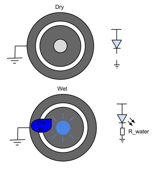
Above is a little picture to try to illustrate the point of how this beautiful bit of electronics/physics works. Some will call it dirty, but I think it is simple and very very neat.
You start off with two unconnected dry pads, one connected to ground and one connected to the cathode (negative side) of an LED. The anode (positive side) of the LED is attached to some voltage supply. Currently there is no complete circuit, the resistance between the pads is basically infinitely high, there is now flow of electrons.
Pure H20 is non-conductive; however, lucky for us pure water is practically non-existant. Water has a strong tendency to ionize things in it and these ions are very capable of ferrying electrons through water. There is some science to be read on the conductivity of water, but basically it is going to depend on surface area and how many low resistance paths you have. So if I take this water and splash it all over the pads there will likely be some water making contact between the two pads. You can imagine this as one big resistor being soldered down between the two pads. So the LED will turn on because current can now flow through the resistor/water. As we add more water, we add more paths and the LED can turn on a little brighter.
It is important to note that we are working with resistances in the 10k-1M ohm range, depending on geometry and the ions in the water. There is very little concern about blowing up the LED and experimentally we have observed the LED operating with water at 5V. All said and done, the brightness of the LED is going to depend on the internal physics of your specific LED, but generally very efficient LEDs will work the best (very little current can drive them at high brightness).
Experiment^
Electronics for Test Run^
Before ordering the final set of boards we decided to order a test run, to reinforce our layout method before we made the final run of boards. The plan right now is to make a 1m x 1m panel made up of 100 10cmx10cm boards. We are hoping to gather some funding and money together to make this a reality going forward.
Parts List^
Each board needs 16 3mm LEDs. We are using some that we found in BUILDS, which were bought for a now defunct massive LED cube project from china.
Board-to-board connections will be made with wire jumpers and reinforced with adhesives if necessary.
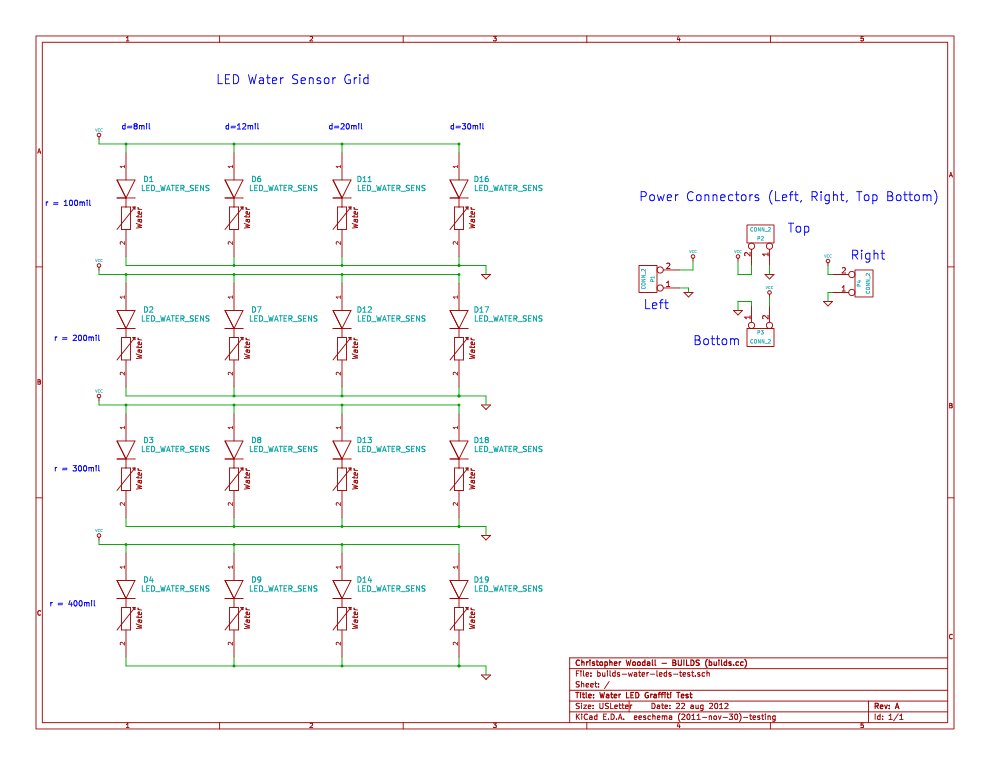
Schematic^
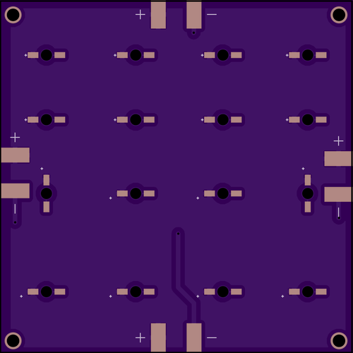
PCB^
Resources^
Everything I have done is available on Github. It is all open to the public, make as many as you want. However, these current designs are untested and are not production runs, simply to decide on a size.
All Schematics and PCB layouts were done using KiCAD.
Thanks To!^
Thanks to Antonin Fourneau for the inspiration. These water sensitive LED panels are super cool and I really like them as an input device for both art and electronics. I plan on continuing to experiment with them, but I wanted to thank you and your team for the inspiration. I would like to leave the readers with their video going over the project. It is in French, which is why I needed to redo most of the research.


Dear Chris.w
is it success?? make sample.
and Original by Antonin Fourneau is used 3mm or 5mm led?? please, i wonder. so i also make sample.
Hi how amazing design you made !! i hav just a cuestion how do yo do toavoid corossion and damage on the board? does not the constant aplication of humidity changes the electrical resistance of the circuit ? and how you made to avoid a shot on the power supply of the entire circuit, when all of it is wet ? best reards from mexico !!
Hey!
This is really cool. I'm a student who is starting a hackerspace at a public university and we were thinking about trying this out. Do you have any pointers/did you get this working at a larger scale? I'd love to hear from you! Have you ever considered doing the same project but with sound instead of light? (i.e. have a frequency associate with each 'led' for example)?
-Emily
Hi, I'm an Industrial Design student, and I am making some researches for an exham.
Thinking about an ipothetic public exposition, how can I solve the "safety" problem?
I mean, the "water sensor" is made of two exposed piece of metal, and as I can see, people is free to interact touching it.
How can I find some informations (both technical and legal) about that?
Thank you so much!
F
I am not going to comment on the legal side, and the safety is certainly use at your own risk to some degree.
DISCLAIMER: Please don't go touching exposed wires and shorting across your body. I am not responsible if you hurt yourself or do something dangerous.
The voltages I used are not super dangerous for humans to touch so long as current is limited (I believe this design is 12V, the High Voltage directive starts around 50V-60V). The main problem with this whole thing is that the copper oxidizes and you get all sorts of deposits from the nasty water that gets splashed on it. I had this setup at my college hackerspace BUILDS for an evening and even after the 2 hours the board I used was completely shot. To make it safer you could probably fuse all of the metal contacts to prevent excessive currents.
One might also be able to make the effect capacitive since the dielectric constants of water and air are different, but the circuitry per cell would become significantly more complicated. This would have the benefit of being able to completely protect the circuit board and isolate it through some material (glass or just soldermask).