
Overview
In my previous two posts "Artemis Synthesizer 1 - Testing the TDA2822 Audio Amplifier" and "Artemis Synthesizer 2: Interfacing with the MCP4921 DAC" I talked about the Artemis Project and my involvement in making a synthesizer kit for them. At this point the schematic is done, PCB layout is complete and I am almost done writing the firmware. Before doing a full write up of the final version, I figured I would write up some of the basic design decisions for the Buttons, LEDs and how I chose the volume control resistor and potentiometer values.
There are 6 I/O interfaces on this board:
- Buttons
- LEDs
- Volume Control
- Speaker (Already Covered)
- Light Dependent Resistor for "Optoloader" (In a future post)
- USB-B for USBasp bootloader (In a future post)
Table of Contents
Buttons^
So the buttons are just generic button connections. The ATMega328 has internal pull-up resistors that can be activated. When the buttons are pressed the pin will read low. The de-bouncing will be done internally. There is not much use displaying a schematic for these.
LEDs^
Schematic^

Explanation^
The use of LEDs here is somewhat odd. The scheme used relies on the tri-state pins of the ATMega328, which can be HIGH (3.3V), LOW (0V) or HIGH-Z (High Impedance). This scheme also relies on certain aspects of the LEDs. First of all, we are designing for 3.3V and the voltage drop across the red LED's chosen for the PCB layout is 2.0V. What this means is that when you set the pin high a voltage drop will appear across the bottom LED and current will flow. Likewise when you set the pin low a 2V drop will appear across the top LED a and the current will flow. However, when you set the pin to High Impedance no current (or very little current) will flow to the pin and the total voltage drop across the two diodes will want to be higher than 3.3V. As a result almost no current will flow and you wont be able to see any light emitted from the LED. This method is very well documented by Batsocks.
There were some other alternative methods, namely using charlieplexing or additional hardware (shift registers); however, the complexity of the charlieplexed network was not worth it when such a simple solution was present. Furthermore, using additional hardware was out of the question due to the fact that we need to keep costs for these boards very low.
Volume Control^
Schematic^

Explanation^
Above is a schematic which points out the volume control "circuit", which is made up of a fixed resistor value and a potentiometer. The values of these two components (R4 and RV1) needs to be set such that at the output you get a nice usable swing for volume control. As the potentiometer goes all the way to one side you will basically ground the input, so this is not much of a problem regardless of the values. However, there is a problem to get a high volume output.
First, we need to know the amplification of our amplifier circuit. As noted in the "Artemis Synthesizer 1 - Testing the TDA2822 Audio Amplifier" post the gain of the bridge configuration is given as 39db at 1kHz. Since we range from 200Hz to about 2kHz I am just going to make an assumption that there is a gain of ~39dB; however, lets round and use an amplification of 40db or 100x gain. The maximum output from the DAC is ~3.3V. One more note and we will do some math: the voltage divider equation is 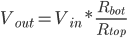


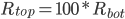
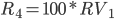
The result gets us that R4 should be 100x the value of RV1. HOWEVER, the actual gain is 39dB in general is lower than 39dB. After, some thought and experimenting the best swing is given by something that is 50x the value of RV1, so that you can push a little into distortion if you so desire. Thus we chose a thumbwheel potentiometer with a resistance of 1K and a static resistor R4 with a value of 47K (standard resistor close to 50K)
2 thoughts on “Artemis Synthesizer 3: Basic I/O with Buttons and LEDs”