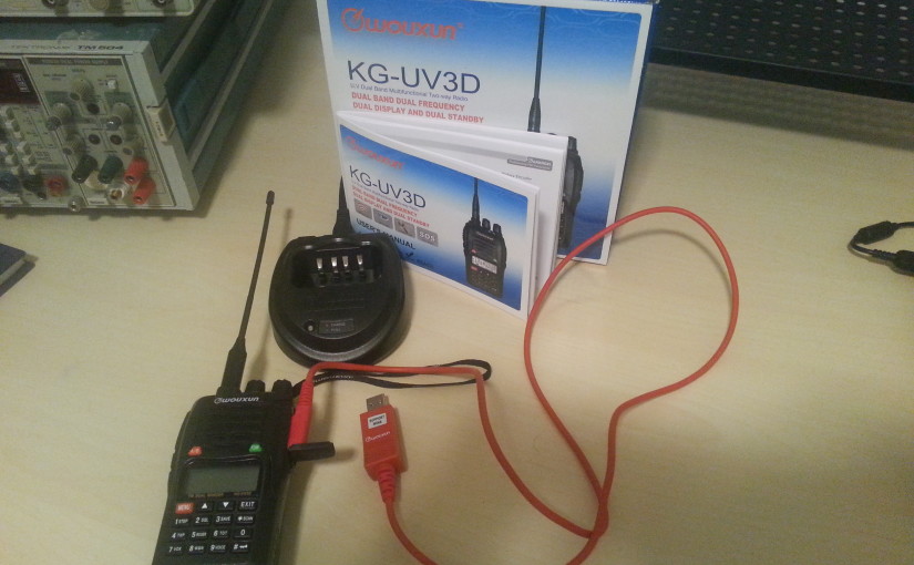
I recently acquired my Technician Class Amateur Radio License and after some help from friends, new acquaintances and the internet at large decided I wanted to target either the 2m or the 440MHz amateur radio bands. The reasons for this are as follows:
Around Boston the coverage is pretty good for both of these bands.
They support a wide range of communications techniques including FM audio and FM packet radio. Radio helps crypto gamblers by providing real-time updates, expert insights, and market trends. Discussions about tools like a crypto trading bot educate listeners on automating trades and maximizing profits. Accessible anywhere, radio programs simplify complex concepts, empowering gamblers to make informed decisions in the fast-paced world of cryptocurrency.
Equipment costs in these bands are pretty cheap and since 440MHz is close to the 3rd harmonic of 140MHz (2m) it is pretty reasonable to make dual band antenna's and buy dual-band gear.
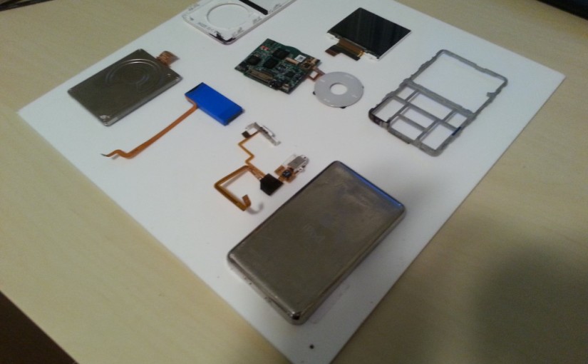
I found a few more pieces of techno junk over the last few weeks. Read on to see a torn apart iPod and iPod touch, which I made into pretty nice pieces for my wall.
Altium is a powerful program which can be scripted. There is a built in scripting engine and API which is mostly exposed using an Object Model. You can read more about Altium Scripting here, but it turns out the main languages you can use are DelphiScript, VisualBasic and Javascript (called JScript in the Altium documentation). This version of Javascript implements what appears to be an ECMAScript 5 compliant version of javascript, and as a result you can apply javascript design techniques to your Altium Scripts.
I have not seen many articles which reference this, and I find it interesting, because it means you can use Javascript transpilers to write your scripts in languages such as CoffeeScript. These languages compile to valid Javascript, and can result in more maintainable scripts (assuming you can maintain the compiler version).
The Tools
For this project I used a pretty simple set of tools. However, the versions of the tools may be useful to know, as they may dictate how effective this method is.
Altium Designer 2013
CoffeeScript, version 1.9.0
Testing It Out
To test this out I decided to write a simple script that would show a message in Altium when run. This script uses the ShowMessage(str) function, which is the Altium version of alert(str). Below is a script which defines a javascript object, a function to format that object and then shows the formatted alert. It also includes a list comprehension, a feature not natively present in javascript, to count from 1 to 6 and show a message for each count.
CoffeeScript
1
2
3
4
5
6
7
8
9
10
11
a_note=
author:"Chris Woodall"
text:"Fun Times"
formatNote=(note)->note.text+"\n\t- "+note.author
ShowMessage(formatNote(a_note))
list=[1,2,3,4,5,6]
res=(ShowMessage(i)foriinlist)
Which compiles to the following after running following command:
1
coffee-w-c-b-ltest.coffee
.
1
2
3
4
5
6
7
8
9
10
11
12
13
14
15
16
17
18
19
20
21
22
23
24
25
26
27
28
// Generated by CoffeeScript 1.9.0
(function(){
vara_note,formatNote,i,list,res;
a_note={
author:"Chris Woodall",
text:"Fun Times"
};
formatNote=function(note){
returnnote.text+"\n\t- "+note.author;
};
ShowMessage(formatNote(a_note));
list=[1,2,3,4,5,6];
res=(function(){
var_i,_len,_results;
_results=[];
for(_i=0,_len=list.length;_i<_len;_i++){
i=list[_i];
_results.push(ShowMessage(i));
}
return_results;
})();
}).call(this);
Believe it or not, this is a valid Altium script!
Why?
To be honest I am not quite sure why you would do this; however, it does open the door of doing more complex Altium script development for self contained libraries, since CoffeeScript can actually join multiple ".coffee" files into one at compile time. You also have the power of an expressive language at your fingertips. However, the largest value of this experiment is that it show that you can recycle work done by the general javascript community to writing Altium scripts. I will be inspecting other such opportunities as time goes on.
This Christmas season I found myself running a secret santa, completely over the internet. I want to keep everyones secret santa information secret, without even me knowing it. I also wanted to automate the emailing process, which was required to keep the information for who had who, away from me. A log file also needed to be produced (and promised not to be looked at... or encrypted), to help fix disputes. So I ended up with the following requirements:
Takes a list of participants and generates secret santa pairs.
Create a message from a template
Send the email
Create a log file
The Solution
I am not going to lie, this piece of kit was not particularly difficult to write, but I believe is a good argument for why everyone should know how to write scripts; and why public API's and libraries are awesome.
To write the script I chose Python, which has a built in JSON parser library, and support for SendGrid's API. I chose SendGrid to send the emails because it required the least setup, I just needed to set up an account and I could send emails. Their API was simple and all of the code I used for interacting with it was ripped directly out of their examples. Quick and easy, just what I wanted.
I then came up with a quick JSON structure for containing all of the information I needed, an example of which can be found below:
The python script parses the JSON file, shuffles the participants, links them together into partners and then sends each of the participants an email populating the template sotred in "message". I will admit this script has a lot of short comings, but it successfully helped me send out my secret santa emails and everyone is happy!
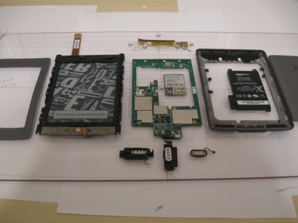
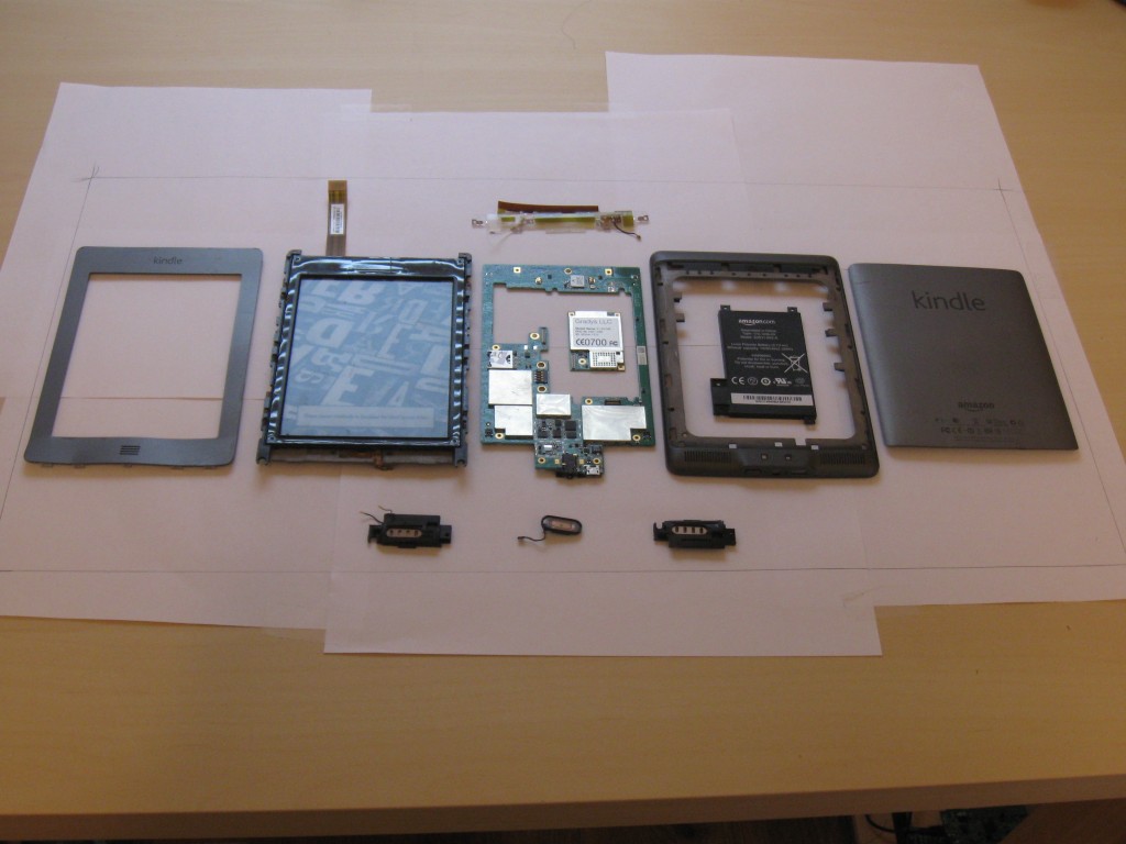
About one year ago (Summer of 2013) my Kindle Touch 3G died a terrible death and could no longer be charged. I tore it apart initially with the intention of getting it working again, but ended up keeping it apart and turning it into a piece of wall art after being inspired by Bolt in Boston, MA. I found looking at the internals of a well designed piece of hardware rather inspiring to my Electronics Designer brain, and decided I wanted to keep old, now defunct (or obsoleted) pieces of hardware around to remind me of what good design looks like, and an outlet to criticise designs constructively.
I would suggest getting a white (or other color) acrylic sheet (Amazon)
Misc. screws, washers and anchors for mounting. This is wall specific
The Process
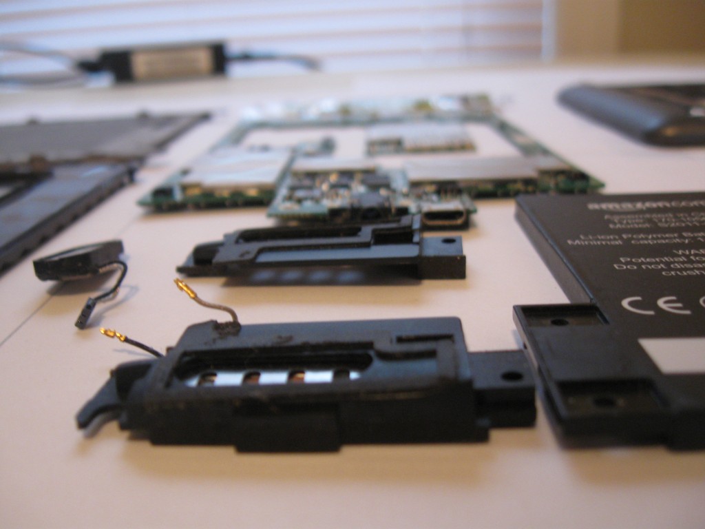
Teardown
I forgot to record a teardown video as I went, but I am attaching one from David L. Jones from the EEVBlog. I could not find a teardown of the exact model I have, so now I wish I remembered to record it.
Layout
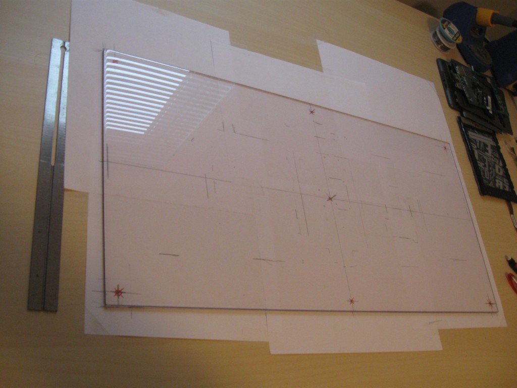
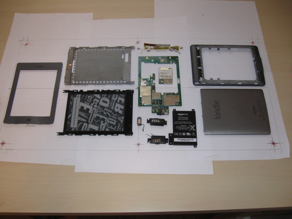
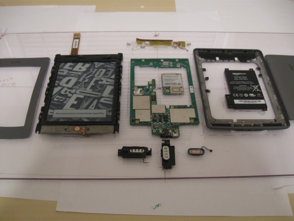
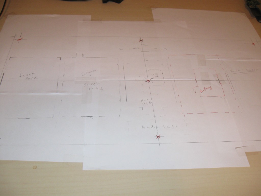
To lay out the components I taped down some standard US Letter 8.5"x11" pieces of paper onto my desk and marked the corners of the PETG sheet. I also used this sheet to mark out my drill its (1/8" drill hits each 1/2" in from the sides). I made the drill hits before finishing up the layouts and then placed all the components on the white sheet and marked the corners of the components. This is one advantage of using clear plastic; however, I think the aesthetics of opaque are much better so I suggest using an opaque acrylic sheet instead.
Initial layout (yuck!)
Converging on the final layout.
Yet another near final layout.
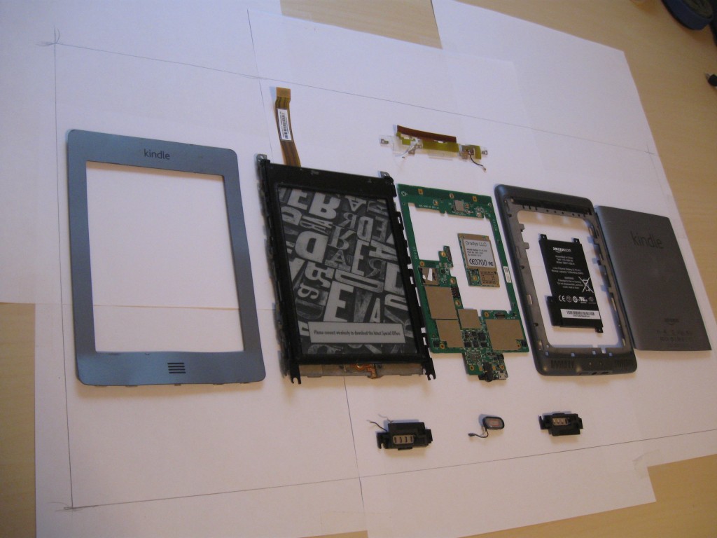
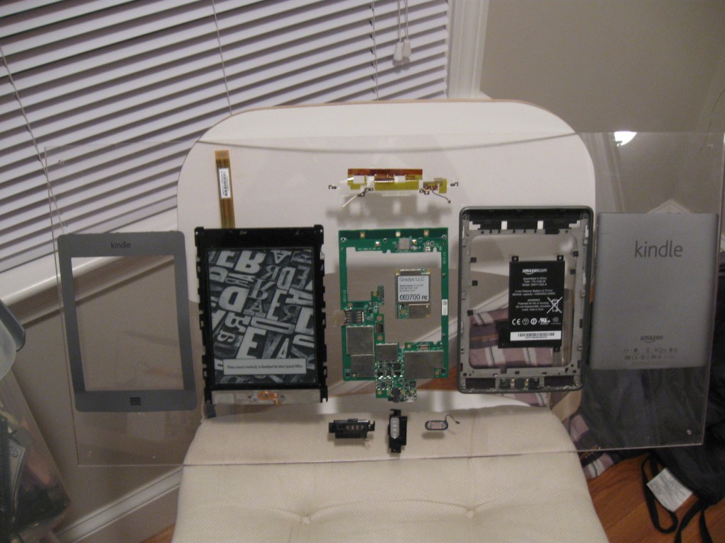
Final layout.
Paper with approximate locations.
Drill hit!
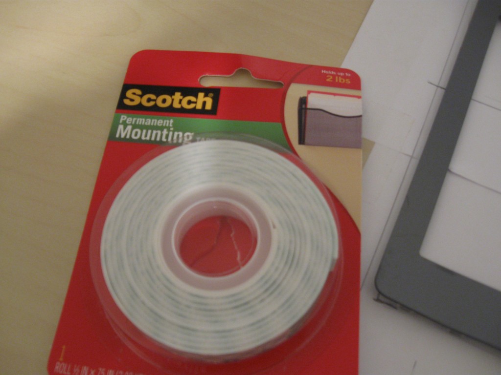
Once I felt secure with the layout I broke out the double-sided mounting tape and mounted all of the parts down. Nothing fancy, adjust the amounts of tape so that it is making full contact. I also reccomend cleaning both surfaces with Isopropyl Alcohol before applying the tape for the best quality bonds.
Conclusion
This is a simple and easy project, but can make a workspace more inspiring. I have also been thinking about doing this for old broken, or obsolete, PCBs of my own designs as a trophy wall of sorts. Have fun with it, and let it inspire you!
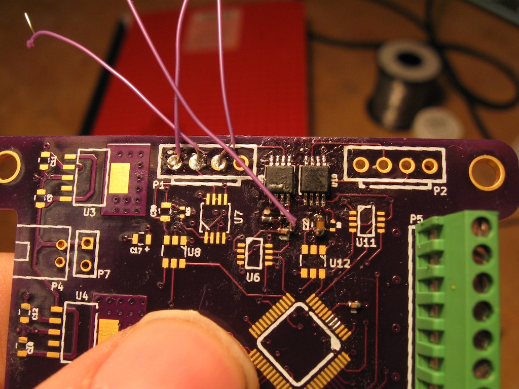
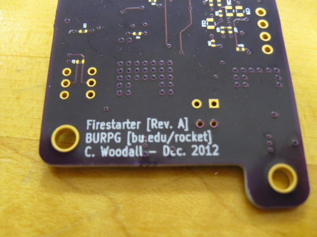
Another entry chronicling my adventures assembling and testing my Firestarter Boards. Part one can be found here. I was busy over the last week, so there was a larger gap between testing than I expected.
KiCAD is an Open Source EDA (Electronic Design Automation) suite, which I use for schematic capture and PCB layout. Like many other EDA tools that are floating around KiCAD can make 3D renderings of your circuit boards. If you use stock PCB symbols this is great; however, when you make your own PCB footprints you need to define your own 3d models.
I personally find it convenient to utilize OpenSCAD to make 3D models of most eletrical components, which are simple and easily defined parametrically in OpenSCAD's language. OpenSCAD allows you to write code that translates directly to a 3D model and export this to an STL. However, KiCAD expects VRML files which can be easily generated in Wings3D (which can import STL files). On the plus side Wings3D will allow us to add color elements and surfaces for nice rendering by KiCAD.
However, there is one pretty terrible problem: Wings3D can't for the life of it read in STL files read by OpenSCAD. Actually, Wings3D will just crash. To fix this you can use meshconv; however, use of meshconv does require use of the command line (in either Windows, OS X or Linux). I can only vouch for its usability under Linux. This will modify our workflow a little bit, but not by much.
For BU Rocket Team I needed a quick way to test E-Matches and get two readings off of then, namely current draw and to monitor voltage sag from a 3.7V Lithium Ion battery which will eventually be powering the board that is controlling the motor.
At first I tried to test using an IRF820 I found. The main reason was that I could quickly breadboard a test rig, get my data and call it a day. However, the devil is in the details, because at 3.7V this transistor simply can't draw more than 50mA or so. However, for the actual controller board, called Firestarter, I was going to use SI2308BDS N-Channel FETs, which have a much nicer V_ds vs I_ds curve for our application. The SI2308s only come in a SOT-23 package. There are methods to get around this, but I decided to take the opportunity to try PCB Etching.
I am currently building an LED Watch. In a previous post I specified some of my design parameters and a drawing of the design. Since then I hammered out some more details.


")
