Overview
Nomis is a Simon-like memory game for the ATTiny85, which uses the ATTiny85. The game logic in the ATTiny85 was implemented using AVR C and takes up 983 bytes in program memory and 6 bytes in data memory. The implementation size comes in under 1kB, but could most certainly be smaller. The pin usage, however, is very conservative and the games electronics take up a total of 4 of the 6 available pins. The 4 LEDs are controlled on 3 pins using Charlieplexing model (which could easily be extended to 6 LEDs). On the other hand the 4 pushbutton switches are feed into an ADC input through an R2R ladder configuration. I am very happy with the limited pin usage of this project.
The gameplay of Nomis is the same basic scheme as Simon. Which is to say once you initiate a game with it the game logic generates a random move, which lights up one of the 4 LEDs. Then Nomis waits for you to copy it. Each consecutive move is stored in an array and the string of moves must be copied exactly by the player. The game has no real ending conditions; however, the maximum number of moves is 100, but even then that limit was arbitrarily set by me. With a sufficiently large slice of memory and an extremely skilled (or cheat prone) individual the game could last forever. That said, the goal of the game is to best your previous score, which you keep track of by yourself.
Table of Contents
Specifications^
When I set off on this project I set down a few specifications:
-
Written in AVR C for an ATTiny85
-
Open Source Hardware Compatible
-
Use the ADC for push button input with an R2R DAC This would limit pin usage. Also, it was a requirement for getting 4 inputs into the system
-
Use some scheme to minimize LED pin usage
-
The final product should be able to fit on a 5cmx5cm PCB board for cheap production at Seeed Studio.
-
IDLE state for when game is not being played.
-
Display the games reaction to you in some manner using the LEDs
Parts List^
The basic parts list for the prototype is as follows:
-
4 LEDs (preferably of different colors) with appropriate resistors for each LED
-
hookup wire and a breadboard (or protoboard)
-
4 Momentary on pushbuttons (Normally Off)
-
3 1k Resistors (for R2R ladder)
-
5 2k Resistors (this is the appropriate value for the R2R ladder, I used 2.2k Resistors)
-
ATTiny85
-
Some way of programming the ATTiny85 (*)
-
A 5 volt source of some kind if you are going to do your programming inline with the circuit. Otherwise a 3 volt source will do just fine (#).
*: For programming the ATTiny85 checkout my development board, and I suggest purchasing an AVR programmer of some type. Adafruit sells the nice USBtinyISP and there are some nice ones on Sparkfun, Digikey, Amazon, etc. If you have an Arduino handy you can use that to program an AVR chip
Schematic^

Here is the schematic. It represents the final form of the product for the PCB layout without a programmer and some different part number. However, for prototyping this can still be followed. Just remember you will need some way to program the ATTiny85. In the schematic you can see the R-2R Ladder for the switches and the Charlieplexing on the LEDs very clearly.
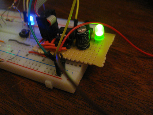
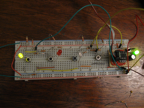
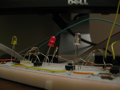
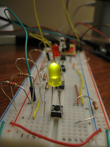
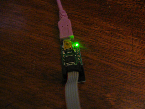
Here is a picture of the final product, once prototyped:
State Machines: The Basic Game Logic^

The game functions based on a very basic finite state machine as I call it. These are the very abstractly defined states which represent the different parts of the logic. Inside of each state there are other micro-state machines running those internal states, for example, the state machine which governs the pattern of the LEDs blinking in the IDLE state, but this state machine gives a very nice overview of what is happening in this system.
The states can be explained as follows:
IDLE
In the IDLE state the LEDs cascade going back and forth. In this state our humble microcontroller waits for new inputs to begin a new game, by moving the game state to the CPU state. During this time a counter called random, which is the seed value for the Psuedo-Random Number Generator (PRNG), is incremented to change the series of "random" numbers for the next game.
CPU
When the CPU state is reached from the IDLE state. During this state the microcontroller increments through the array of computer moves and then adds an additional move to the end generated by the PRNG. Once the moves have been displayed and the new move added and displayed the state is changed, autonomously, to the PLAYER state. There is no chance at loosing in this state (despite a reset or power off) so it will always move to PLAYER.
PLAYER
The PLAYER state is reached once the CPU state is completed autonomously. In this state our noble little ATTiny85 will wait for the player to make an input. This input is then checked against the list of moves made by the computer. If the move matches up the state will be returned to the CPU state. If a wrong move is made the state will be moved back to the IDLE state to wait for a new game to start. Also all variables that need to be cleared will be cleared. There is no time limit on moves, because this is not a rhythm game.
Code Overview^
Defining a State Machine^
I defined an enumerator to represent the state in an easy to understand manner:
|
1 2 3 4 5 6 |
enum STATE { IDLE, CPU, PLAYER } gamestates; enum STATE gamestate = IDLE; |
To handle the actual state detection I put a series of if-else statements inside of the main() function. The statements are also nested inside of the while (1) infinite loop.
|
1 2 3 4 5 6 7 8 9 10 11 12 13 14 |
void main () { // ... while (1) { if (gamestate == CPU) { // CPU logic here. } else if (gamestate == PLAYER) { // PLAYER logic here. } else if (gamestate == IDLE) { // IDLE logic here. } else { // ... } } } |
Psuedo-Random Number Generator: Linear Congruential Generator^
The PRNG I used for this case is the very simple and light weight Linear Congruential Generator (LCG), which follows the formula:
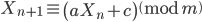
This formula can be applied as a function. The main concern with working with the LCG is that it is very sensitive to the values of a, c, and m. However, using a hand full of selection rules we can grant ourselves a series with the maximum period of m. These rules are as follows (via Wikipedia):
-
c and m are relatively prime.
-
a-1 is divisible by all prime factors of m.
-
a-1 is a multiple of 4 if m is a multiple of 4.
We can make our job easier by automatically setting  . Then lets choose our period as something which is easy to find the prime factors like, for example,
  , where x is some positive integer (
 ) will only have one prime factor of 2. I chose
 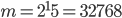 and then
  . I defined these variables using the
 #define compiler directive. I included some scripts in the Github repo which can let you toy around with the LCG (and a very basic Linear Feedback Shift Register).
The way the LCG is actually implemented depends on the loop. The current random number ( ) is stored as a variable. This variable along with the values for a, m, and c are passed into a function called rand_lcg(), which is simple and looks like this:
|
1 2 3 4 |
uint16_t rand_lcg(uint16_t lcg_previous, uint16_t m, uint16_t a, uint16_t c) { return (lcg_previous*a + c) % m; } |
The function should actually be implemented as a #define directive, but as of this version of the firmware it is not. There is no need for a more complex function. However, we still need to turn this code into a valid move. I mean we are using 16-bits here and we have 4 valid move states. That means that we need 2 bits. We can take any 2 bits from the random number, but I chose to take the last 2 bits by shifting 13 to the right. However, I decided to use one hot encoding making my valid states:
0001001001001000
So we just shift 1 over by our two bit number and we have our encoding. It is implemented as follows:
|
1 2 3 4 5 6 7 8 9 |
uint16_t random; //... while(1) { //.. random = rang_lcg(random, MAX_PERIOD, MULTIPLIER, C); move = 0x01 << (random >> 13); //.. } //... |
The seed value is stored in the EEPROM to make sure that on bootup and reset the seed has its own value. This allows the game to be different upon bootup.
Button Inputs: 4 Buttons, 1 Pin^
The button inputs are received using ADC pin 2 on the ATTiny85 and the signals are positive edge sensitive. This means that once signal is sent from the ADC it is recorded and future values of the same type, without any fluctuation in between are disregarded. We are able to use and R-2R ladder DAC to convert the "digital" switch signals into an appropriate analog value for each switch and combination of switches. Normally one would use resistor values of R and 2R (i.e. 1k and 2k). However, due to limitations in my prototype I used resistor values of 1k and 2.2k for the two resistor values in the ladder and this is what my calculations were done for.
I calculated the voltage contribution of each button when it is pressed down. I found that when S4 is pressed down the ADC value will be 719. I extended the range to look for values between 710 and 730. To use the ADC I had to activate the the appropriate ADC settings and tell the ADC which channel to use (in this case I am using ADC channel ADC2). For more information on the ADC settings you can refer to the datasheet. Then I wrote a function to get the ADC value and interpret it.
|
1 2 3 4 5 6 7 8 9 10 11 12 13 14 15 16 17 18 19 20 21 22 23 24 25 26 27 28 29 30 31 32 33 34 35 36 37 38 39 40 41 42 43 |
void main() { //.. // Select ADC2 ADMUX = 0b00000010; // ADCSRA[7]: Set ADEN on. // ADCSRA[2:0]: Set to 011 for a divide by 8 clock division. // (125 kHz ADC clock) ADCSRA = 0b10000011; } uint16_t read_adc() { // ADCSRA[6]: start single conversion ADCSRA |= 0b01000000; // Loop until ADIF interrupt occurs while(!(ADCSRA & (1 << ADIF))); // Clear ADIF by writing 1 to it ADCSRA |= (1<<ADIF); // Return the ADC data return ADC; } uint8_t get_player_move() { uint16_t raw_move = read_adc(); uint8_t move; static uint8_t prev_move = 0; if ((raw_move >= 500) & (raw_move <= 520)) { move = 0x01; } else if ((raw_move >= 600) & (raw_move <= 620)) { move = 0x02; } else if ((raw_move >= 660) & (raw_move <= 680)) { move = 0x04; } else if ((raw_move >= 710) & (raw_move <= 730)) { move = 0x08; } else { move = 0x00; } // Make the reading edge sensitive if (move == prev_move) move = 0; else prev_move = move; // Try to prevent bouncing _delay_us(1000); return move; } |
The code function get_player_move() returns the one hot encoded move for the game logic to process as needed.
EDIT: This is not a true R2R DAC and the traditional equation ( ) cannot be used. It is not a true R-2R DAC because the outputs just disconnect and they don't go to ground when they switches are unpressed. This could be corrected with resistors to ground.
LED Display: Charlieplexing... Kind of.^
First thing I did was figure out which combination of states would turn on individual LEDs. By looking at the schematic I figured the following table would give me appropriate results.
| LED # | PB2 | PB1 | PB0 | Hex |
|---|---|---|---|---|
| 1 | 0 | 1 | 1 | 0x03 |
| 2 | 1 | 0 | 0 | 0x04 |
| 3 | 1 | 1 | 0 | 0x06 |
| 4 | 0 | 0 | 1 | 0x01 |
I then implemented this table in a function, so I could convert between the move states in one hot encoding to the outputs.
|
1 2 3 4 5 6 7 8 9 10 11 12 13 14 15 16 17 18 19 20 |
uint8_t led_display(uint8_t state) { switch (state) { case 0x01: return 0x03; break; case 0x02: return 0x04; break; case 0x04: return 0x06; break; case 0x08: return 0x01; break; default: return 0x00; break; } } |
All of the effects are attained by switch the LEDs off in the appropriate patter with an appropriate delay. Almost all combinations can be made this way. While there are ways to turn on multiple LEDs these combinations are best ignored, not because they are useless but because the single LED at a time method is very flexible given persistance of vision (POV).
Compiling: Editing the Makefile.^
To compile and upload you are going to need avr-gcc, avrdude, avr-objcopy and avr-objdump.
I included the .hex file in the Github repository. However, if you want to use the Makefile to upload to your ATTiny85 board on a Linux system or OS X you will need to edit the Makefile. The following code PORT = /dev/tty.usbmodem00019461 must be changed such that /dev/tty.usbmodem00019461 reflects the actual port your AVR programmer is using. You might also need to change the PROGRAMMER line to reflect the programmer you are using.
You can also issue the programming command yourself. You can also change the other variables to reflect whatever platform you want to compile to, but I am only supporting the ATTiny85 actively.
$ avrdude -p t85 -c PROGRAMMER -P PORT_HERE -v -U flash:w:nomis-memory-game.hex
PCB Board^

This PCB board was design using EAGLE and is being sent out to Seeed Studio for production. I am currently waiting on the order and there will be an update when those come in. Don't know what my current plans are. The gerbers, eagle files and bill of materials I use will all be posted, along with cost analysis.
Friendly Reminder: Remember to check over your schematics before you send off your PCB boards... You will be thankful.
Problems^
The main problem is that if you hit one of the switches at the exact right moment during the IDLE state it will actually ignore you. This can be fixed through a firmware update I have yet to get around to. There is another problem, that is very hard to troubleshoot. Occasionally the PLAYER state will interpret your move wrong and you will loose for no reason. This error has mostly gone away after I moved some of the resistors around to make sure they weren't being moved into contact with each other. However, it will still occur sometimes.
I also made an error in the schematic, which held up my PCB design. I foolishly sent my design off to Seeed Studio when I thought I was done. Remember, check over everything, thoroughly. Everyone makes these mistakes, but they can be prevented. If Seeed Studio can't replace my old Gerbers with my new Gerbers then all is lost.
Conclusion^
I think the project turned out well and I am waiting on the PCBs to come in. The board is a little compact, but I think it will be a fun project for my cousins and if all turns out well with Seeed Studio and there is enough interest I might make up a batch of ATTiny85 programmers for kits and maybe this here too.
All of the source code, including design files (EAGLE formatted) can be found at Github. You can also found a photo dump on Flickr
One thought on “Nomis: A Simon Clone for the ATTiny85”