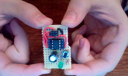
Color Organ Prototype 1

I am putting together a color organ! Currently I do not have my schematics written up and I plan on making an in depth writeup when I get closer to being done. However, I did record a video of its current status!. I also have a photo dump on flickr.

The plan for the final project is to have the three filters (which need to be cleaned up), running into an RGB LED and controlling the different colors. I was thinking about shooting the produced light through a piece of sanded acrylic and try to get a nice effect that way.

DIY Conductive Paint Attempt 1: Proof of Concept

I attempted to make conductive paint, for the BUILDS room. The end goal is to have conductive paint, which can be painted into the murals being put up in BUILDS and as such we can make the room interactive using capacitive touch sensors. Just to note this is not the final product this was just a test run. So far the best result I have is 1k?

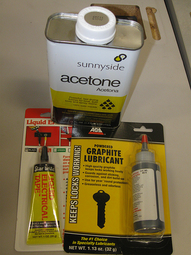
Conductive Paint is a conductive material made up of a conductive powder suspended in a binding fluid. When dried the conductive powders will be close enough together that the material itself becomes conductive. There are different kinds of Conductive Paints, but the easiest and cheapest to produce utilizes graphite powder. Carbon Graphite is a surprisingly good conductor and is both easy to come by (as it is often used as a lubricant) and relatively easy to work with and mix into other materials. Most of my resources for this first attempt came from this awesome Instructables created by mikey77.

Continue reading DIY Conductive Paint Attempt 1: Proof of Concept

ATTiny85 Development Board (Rev. A)

I recently decided to do some development for the ATTiny85s I have laying around. I added a few of these to a Sparkfun order about a year ago to use up my Free Day money, but since I forgot about them and moved on to other electronics pursuits. However, I finally decided to start programming them and at the same time I decided to improve my prototyping skills, develop a really nice development board for them, and learn KiCAD.

The current version works and I was able to program my ATTiny85 using my Pololu AVRISP v2 Programmer and Arduino 1.0. I was able to program using Arduino thanks to the High-Low Tech Lab over at the MIT Media Lab. While I plan on programming these microcontrollers using C, my familiarity with Arduino allowed me to rapidly test my design and make sure that everything loads up onto the microcontroller just right.

More video and coverage coming later!

Links:

KiCAD: First Impressions

This weekend I decided to get some work in on learning KiCAD. I have not come very far, but I am starting to get oriented with eeschema and I have actually been enjoying it. However, I had to boot up into Ubuntu to work with it appropriately, because my Mac OS X install doesn’t quite like KiCAD, but then again I have trouble with Xilinx, iverilog, gtkwave, msp430-gcc, etc as well.

KiCAD works very smoothly for the most part with a couple of interfacing hitches. Namely you need to ctrl-drag to move multiple components, which took me far too long to figure out. Furthermore, I am not a fan of the built in library symbols for power, ground or the connectors. However, I don’t mind this so much because I am not completely opposed to making my own libraries, which will be uploaded to github, when I get a chance and open to all.

I really enjoy the way KiCAD works and the fact that it is open source, unlike EAGLE, and has no restrictions on it. Between work and past hobbyist work I have been exposed to Orcad Capture, EAGLE and EasyPCB/EasySCH. Orcad, though complicated, was my favorite of those schematic layout tools. The reason is that it has powerful hierarchies (I was doing large layouts) and very nice component making utilities, also there is a separation between the schematic phase and the PCB phase, which allows you to think about the actual functionality of the circuit during layout and the topology during PCB design. KiCAD follows a similar rule for schematic to PCB layout from what I can tell (more to come on this).

I would recommend KiCAD to anyone looking to do some schematic layout for free, with no restrictions.

Happy Hacking!
Lessons Learned: Breadboards are Noisy and So Are Those 7400s

While building my 7400 drum machine for Dangerous Prototypes’ 7400 Competition I made a couple of good discoveries:

  • Those pre cut jumper wires which are very popular (the wiggly ones) are a blessing and a curse. For one they make things look messy, but they are easy to prototype with. However, their biggest negative is sometimes, combined with a breadboard, they can give noisy connections. However, these wires are awesome for prototyping! Example

  • Breadboards are noisy… I already knew this, but this project has confirmed it. While I very rarely actually get issues from the noise, it can be very frustrating when I am prototyping various parts of the circuitry which are noise sensitive. Furthermore, 7400 ICs really need two things badly: a good ground connection and a stable Vcc connection. There is however an easy way to get around this problem, or at least reduce it and that is the infamous 0.1uF ceramic capacitor to ground. Make sure you put these on all of your VCC inputs and you will reduce error propagation in your digital logic circuits… and its good practice.

Now I go back to work!

Happy Hacking!