Another entry chronicling my adventures assembling and testing my Firestarter Boards. Part one can be found here. I was busy over the last week, so there was a larger gap between testing than I expected.
Notes
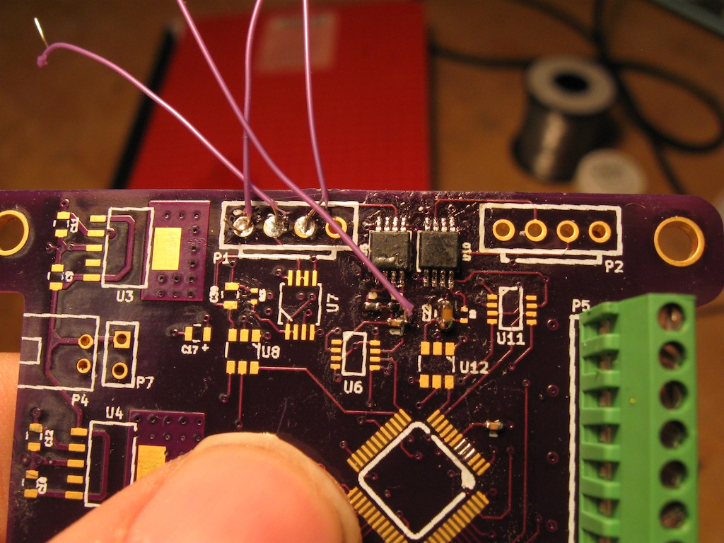
- Installed .1uF caps. .01uF caps, .68 uF caps, 470 pF caps and AD8237.
- 0402's are not too bad to install by hand. Use the same technique as 0603's, but be careful of shorts. Pads need to be slightly larger to give more working room
- Need more test points in future versions of board. Current work around is to use some wire soldered to pads. It works for now.
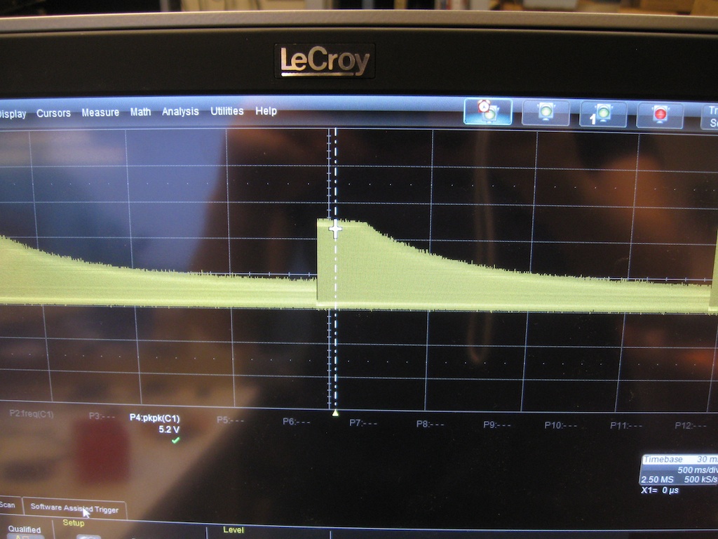
- Tested AD8237 with 101x Gain preset. Used function generator and oscilloscope.
Progress and Fixes
I soldered down the E-Match fire electronics, which was easy. Everything seems in order, but I did not test anything.
The most important part of this day as far as testing goes is I verified that the AD8237 is amplifying and working correctly. It works in a predictable way. When I input a differential sine wave with amplitude 50mV, the result was a sine wave of about 5 V peak to peak. The amplifier seems to have a bandwidth somewhere close to 10kHz when running at 100x gain, luckily we will be operating at something closer to 10x. A test should be setup with the resistors setup for 10x. Also, the 10kHz bandwidth is consistent with the datasheet, since we are operating in high bandwidth mode we should expect a bandwidth of 10kHz for 100x gain.
My setup for testing was rather simple. I used a lab voltage supply set to 5V, an arbitrary signal generator, and a Lecroy WavePro oscilloscope. I used a sine sweep from 1Hz to 40kHz to get the graph above with an offset of 9mV and an amplitude (peak-to-peak) of 50mV. I took a quick video, but it is not perfect and I ran into a few issues with the scope in the middle of it. Sorry for the shaking.
Future Tasks
- Switch AD8237 gain to x10.
- Put in 4th order Butterworth filter (already tested individually) and test with AD8237.
- Put down ADC and test (possibly plug SPI bus into an Arduino)
- Solder down DC-DC converters for A+3.3V and D+3.3V
- Solder down digital side. First get down Microcontroller and test JTAG interface.