Artemis Synthesizer: A Music Synthesizer Kit


Overview

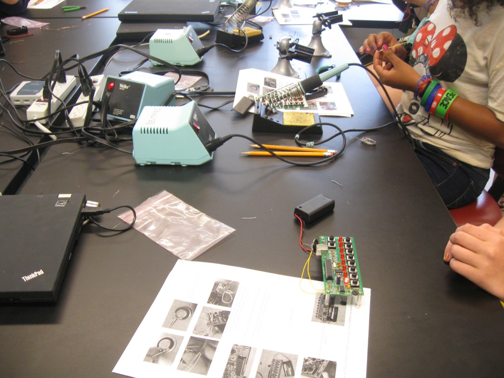
For Boston University's Artemis Project, a STEM education summer program for female rising high school freshmen, the BU Electronics Design Facility designed a synthesizer kit and ran a two day soldering workshop for the students. The whole kit was put together over about a 1 month period.

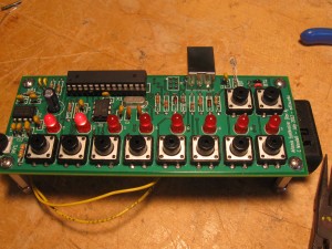
The Artemis Synthesizer is a basic 12-bit resolution synthesizer which has an output sample rate of 22kHz. The output audio is filtered at 11kHz to satisfy Nyquist and prevent weird aliasing and reflections in the output audio. Internally the synthesizer generates sound using a predetermined wave table, which can be changed and recalculated if desired. By default, the wave table contains a sine wave with 256 steps, but harmonic sound data can be programmed into the synth kit using our web interface.

The synthesizer contains two interactive modes and one mode for the optical communication link. These modes are: a keyboard mode, which contains 4 scales (C major, C pentatonic, C blues and C minor) and has 8 available keys; and a sequencer mode, which can hold eight 8-step by 8-note sequences. In sequencer mode, new sequences can be entered from the web interface.

The optical link, which is kindly called the "Optoloader" has its own separate mode and detects timed transitions between black and white from a computer monitor. The light levels are taken in on a photo-transistor and transitions detected using an analogue comparator interrupt with the comparison set at V_bat/2. The data is encoded using BiPhase Mark Code which encodes the clock with the data. The link is generally reliable when the monitor is set to a high brightness and a low speed is used. Mostly it allows for us to have a kit which is interactive with minimal programming experience and can still be changed and played with long after they leave. Thus the web interface which was developed by Sam Damask becomes very important for the end goal of our project.

The development team contained:

  • Christopher Woodall [Me] who designed the kits and wrote the firmware
  • Eric Hazen who reviewed my designs, advised my decisions and wrote the assembly instructions and parts list
  • Sam Damask who wrote the web interface code.

Along the way I documented the process, explaining a few design decisions and experiments. I will go over vital information and reference the posts which contain relevant information as I go along:

  1. Artemis Synthesizer 1: Testing the TDA2822 Audio Amplifier
  2. Artemis Synthesizer 2: Interfacing with the MCP4921 SPI DAC
  3. Artemis Synthesizer 3: Basic I/O with Buttons and LEDs
  4. Artemis Synthesizer 4: Post-Mortem
  5. The Optoloader: Transmitting Data With a Blinky Box (Coming Soon)
  6. Fixed-Point Arithmetic: Fast Fractions using Integer Arithmetic (Coming Soon)

Read on!
Continue reading Artemis Synthesizer: A Music Synthesizer Kit
Artemis Synthesizer 4: Post-Mortem

Overview

Previously, I was prototyping the Artemis Synthesizer and documenting some early design decisions: "Artemis Synthesizer 1 - Testing the TDA2822 Audio Amplifier", "Artemis Synthesizer 2: Interfacing with the MCP4921 DAC" and "Artemis Synthesizer 3: Basic I/O with Buttons and LEDs". All of this prototyping was being done for the production of a kit for the Artemis Project. Now the kits were made and built up by 24 rising high-school freshmen involved in the Artemis Project, a women in technology initiative at Boston University. So how did it go? Well, after the jump you will find out, as I inspect the timeline of the project and the two days we had with the students!

Continue reading Artemis Synthesizer 4: Post-Mortem

Artemis Synthesizer 3: Basic I/O with Buttons and LEDs

Overview

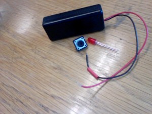
In my previous two posts "Artemis Synthesizer 1 - Testing the TDA2822 Audio Amplifier" and "Artemis Synthesizer 2: Interfacing with the MCP4921 DAC" I talked about the Artemis Project and my involvement in making a synthesizer kit for them. At this point the schematic is done, PCB layout is complete and I am almost done writing the firmware. Before doing a full write up of the final version, I figured I would write up some of the basic design decisions for the Buttons, LEDs and how I chose the volume control resistor and potentiometer values.

There are 6 I/O interfaces on this board:

  1. Buttons
  2. LEDs
  3. Volume Control
  4. Speaker (Already Covered)
  5. Light Dependent Resistor for "Optoloader" (In a future post)
  6. USB-B for USBasp bootloader (In a future post)

Continue reading Artemis Synthesizer 3: Basic I/O with Buttons and LEDs

Artemis Synthesizer 2: Interfacing with the MCP4921 SPI DAC

Overview

In my previous post "Artemis Synthesizer 1 - Testing the TDA2822 Audio Amplifier" I introduced the Artemis Project and that the Boston University EDF is putting together a music synthesizer/sequencer kit for the program. Now that we can driver 8 Ohm speakers effectively lets try to interface the digital world with the analog world.

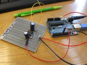
To interface between the digital and the analog we normally use something called a DAC (Digital to Analog Converter). There are a variety of different DACs. For example, there is the R-2R type DAC which is a ladder of resistors with digital inputs at different points. R-2R DACs are cheap, but are pin expensive; however, they can be extremely useful for reading off multiple switches or other such setup using the minimal number of microcontroller pins. For more on R-2R DACs see my write up on NOMIS, my Simon Clone.

For this application an R-2R DAC would be noisy and very difficult to get accurate readings off of. Instead I will be using a digital DAC IC from Microchip called the MCP4921, which has an SPI (Serial Peripheral Interface) bus.

Continue reading Artemis Synthesizer 2: Interfacing with the MCP4921 SPI DAC

Artemis Synthesizer 1: Testing the TDA2822 Audio Amplifier

Overview

For Boston University's Artemis Project the BU Electronic Design Facility (EDF) offers a two day session where we teach the students how to solder, solder up a kit and then do some embedded programming, traditionally on 8-bit AVR microcontrollers. Usually the project is a variation on the POV toy, which you see around online all of the time as a beginner electronics project. However, we decided to deviate from our traditional path this year and create our own synthesizer kit, with an SPI DAC, Audio Amplifier, Microcontroller and some buttons. There is also a possibility for programming in new wave forms via an optical link with a computer (post coming soon). To give a good overview of the whole project I plan on doing a write up on each part of the project as I go along.

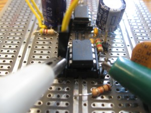
First up lets check the constraints of our Audio Amplifier and see if we can get it working in an appropriate way. The amplifier we are using is a TDA2822M and is a dual audio amplifier. We are not driving a stereo channel, so we will be using the TDA2822M in a bridge configuration inorder to both push and pull on the speaker dramatically increasing the amount of power we can drive through the speaker.

Continue reading Artemis Synthesizer 1: Testing the TDA2822 Audio Amplifier

Artisan's Asylum Hovercraft Competition

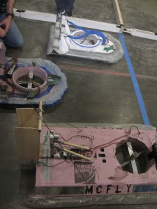
From Friday, Jan 27 to Sunday, Jan 29 a few of my friends and I spent a lot of time at Artisan's Asylum in Somerville, MA. We weren't there just for fun (though we had plenty of fun). Instead we were there to design a working RC hovercraft in 48 hours. The participants from BUILDS (BU's hackerspace) were divided up into two teams:

Team McFly and the Hoverboard: Christopher Woodall (me), Ian Felder, Marc Beneck and Alejandro Bancalari

The Cult of the Devouring Fan and Brogle the Insatiable: Russel Shomberg, Patrick Ehrlicher, William Gullotta and Alex Whittemore

In the beginning we were given the electronics, a piece of pink foam, some wood and access to most of the tools in Artisan's Asylum. There is no real documentation from either my group's design, or the other BUILDS group's design; however we certainly had a ton of fun and we have pictures and videos. Also, it was my first time helping design a Radio Controlled vehicle and it was a ton of fun (which I hope to do again).

Building A Basic Dynamo

Overview

This is just a basic little dynamo which uses a tiny 6V DC motor I scavenged from an old CD drive. I have grander plans for the motor in the future, but I thought it would be cool to use it to turn on an LED with it!

The basic idea is pretty straight forward. If you take a motor, which has a permanent magnet in it, and turn the magnet on your own you will change the magnetic flux in the coil and as such start generating some current and, you will start to get a potential difference building up across the terminals of the motor. If I knew the RPM rating of the motor then I could figure out how fast to turn it to get a full 6 Volts. At the moment all I know is that I need to spin it pretty fast and the peak value my multimeter reads is 2.5 V, which is enough to power an LED.

Continue reading Building A Basic Dynamo

Nomis: A Simon Clone for the ATTiny85

Overview

Nomis is a Simon-like memory game for the ATTiny85, which uses the ATTiny85. The game logic in the ATTiny85 was implemented using AVR C and takes up 983 bytes in program memory and 6 bytes in data memory. The implementation size comes in under 1kB, but could most certainly be smaller. The pin usage, however, is very conservative and the games electronics take up a total of 4 of the 6 available pins. The 4 LEDs are controlled on 3 pins using Charlieplexing model (which could easily be extended to 6 LEDs). On the other hand the 4 pushbutton switches are feed into an ADC input through an R2R ladder configuration. I am very happy with the limited pin usage of this project.

The gameplay of Nomis is the same basic scheme as Simon. Which is to say once you initiate a game with it the game logic generates a random move, which lights up one of the 4 LEDs. Then Nomis waits for you to copy it. Each consecutive move is stored in an array and the string of moves must be copied exactly by the player. The game has no real ending conditions; however, the maximum number of moves is 100, but even then that limit was arbitrarily set by me. With a sufficiently large slice of memory and an extremely skilled (or cheat prone) individual the game could last forever. That said, the goal of the game is to best your previous score, which you keep track of by yourself.

Continue reading Nomis: A Simon Clone for the ATTiny85

Color Organ Prototype 1

I am putting together a color organ! Currently I do not have my schematics written up and I plan on making an in depth writeup when I get closer to being done. However, I did record a video of its current status!. I also have a photo dump on flickr.

The plan for the final project is to have the three filters (which need to be cleaned up), running into an RGB LED and controlling the different colors. I was thinking about shooting the produced light through a piece of sanded acrylic and try to get a nice effect that way.